
008
Guided Build
Beginner
RGB Light
One PWM channel makes brightness. Three channels make color.
Mission: mix your own color
An RGB LED is three LEDs in one body: red, green, and blue. By changing the brightness of each channel, you can mix colors like a tiny display pixel.
This is also your first lesson with multiple PWM outputs working together.
Color mixing
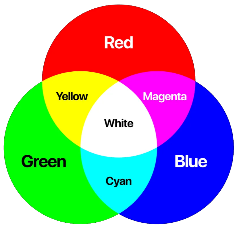
This is additive color mixing because you are combining light.
- Red plus green makes yellow.
- Red plus blue makes magenta.
- Green plus blue makes cyan.
- Red plus green plus blue makes white when the channels are balanced.
Real LEDs are not perfectly balanced, so your white may look slightly tinted. That is normal.
RGB LED pin map
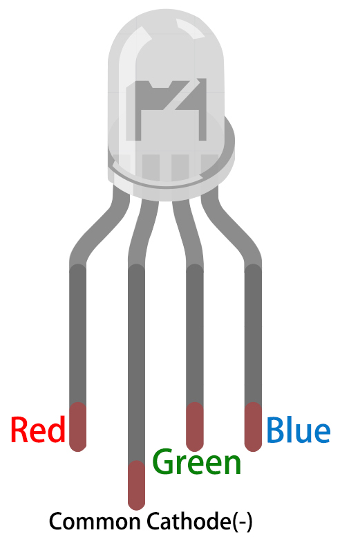
The kit RGB LED is common cathode. That means the shared longest pin goes to GND.
The separate red, green, and blue pins each need their own resistor path. Do not use one resistor on the shared cathode for this beginner build; each color channel should be current-limited independently.
Circuit map
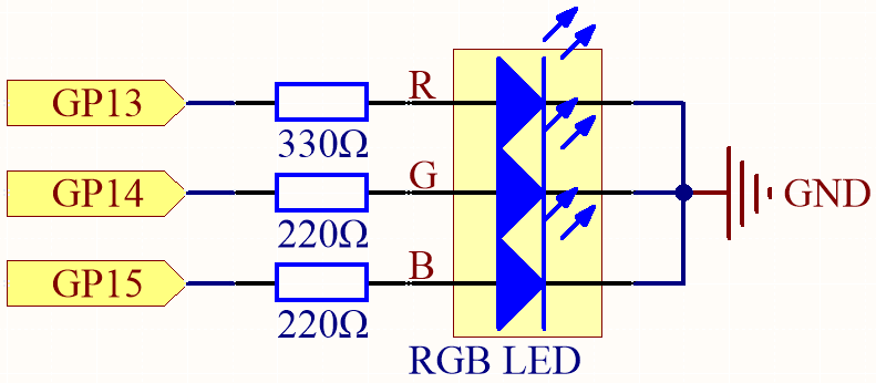
The three PWM channels work like three dimmers:
- GP13 controls red.
- GP14 controls green.
- GP15 controls blue.
- The common cathode goes to GND.
SunFounder uses a larger resistor for red because red LEDs often reach similar brightness at a lower forward voltage than green or blue.
Breadboard wiring
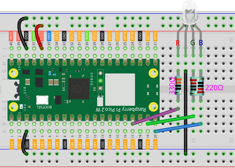
Wire with power disconnected:
- Common cathode to GND.
- Red channel to GP13 through a resistor.
- Green channel to GP14 through a resistor.
- Blue channel to GP15 through a resistor.
If a color does not match the code, do not panic. That usually means two color legs were swapped.
Code: color cycle
from machine import Pin, PWM
from time import sleep

red = PWM(Pin(13))
green = PWM(Pin(14))
blue = PWM(Pin(15))

for channel in (red, green, blue):
    channel.freq(1000)

def scale(value):
    return int(value * 65535 / 255)

def set_color(r, g, b):
    red.duty_u16(scale(r))
    green.duty_u16(scale(g))
    blue.duty_u16(scale(b))

colors = [
    ("red", 255, 0, 0),
    ("green", 0, 255, 0),
    ("blue", 0, 0, 255),
    ("yellow", 255, 180, 0),
    ("cyan", 0, 255, 255),
    ("magenta", 255, 0, 255),
    ("white", 255, 180, 140),
]

try:
    while True:
        for name, r, g, b in colors:
            print(name)
            set_color(r, g, b)
            sleep(1)
finally:
    set_color(0, 0, 0)
    for channel in (red, green, blue):
        channel.deinit()
How the color code works
red, green, and blue are three PWM output objects. Each one controls one LED channel.
for channel in (red, green, blue): sets the same frequency on all three channels without writing the same line three times.
scale(value) converts a familiar 0-255 color value into MicroPython's 0-65535 duty_u16 range.
set_color(r, g, b) is a helper function. It takes three color values and sends the scaled brightness to the three PWM channels.
colors is a list of tuples. Each tuple contains a name plus red, green, and blue values.
print(name) writes the current color to the Thonny shell so you can compare what the code thinks it is showing with what your eyes see.
Debug checklist
If no colors light:
- Check that the common cathode goes to GND.
- Check that each color channel has a resistor.
- Confirm GP13, GP14, and GP15 match the code.
If red and blue are swapped, swap the wires or update the pin numbers in code.
If white looks too red, lower the red value in the white tuple. Color balancing is normal with real LEDs.
Remix: make a status palette
Create your own named color list:
- charging: orange
- ready: green
- warning: red
- thinking: blue
Then replace the color cycle with your status palette. You are building the color language a future project could use.
Checkpoint
Mark complete when:
- Red, green, and blue all light under code control.
- You made at least three mixed colors.
- You can explain common cathode.
- You can explain why scale() is needed for 0-255 color values.
Private Dev Log
Write a short build note:
1. My best color was...
2. One wiring issue I checked was...
3. A project that needs a status color is...
References
Primary build reference:
https://docs.sunfounder.com/projects/pico-2w-kit/en/latest/pyproject/py_rgb.html
MicroPython API reference:
https://docs.micropython.org/en/latest/library/machine.PWM.html