
005
Guided Build
Beginner
Blink an External LED
The built-in LED proved the Pico could listen. Now make a separate part on the breadboard obey your code.
Mission: make your first outside light
This is your first real output circuit. The Pico will still run a tiny loop, but now the electricity leaves the board, travels through an LED and resistor, then returns to ground.
The goal is not just a blink. The goal is to understand the path: GPIO pin, resistor, LED, ground. When you can trace that path, debugging gets much easier.
Parts used
Use the lesson sidebar to open each part page before wiring.
- Raspberry Pi Pico 2 W: the controller.
- Breadboard: the temporary circuit workspace.
- Jumper wires: the roads between parts.
- 220 ohm resistor: limits LED current.
- LED: the output.
The resistor can go on either side of the LED as long as it is in series with it. What matters is that current must pass through the resistor and the LED, not around one of them.
Circuit map
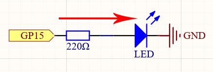
Read the schematic as a story:
1. GP15 can output 3.3V or 0V.
2. Current is limited by the resistor.
3. The LED only lights when it faces the correct direction.
4. GND completes the return path.
Power off while changing wires. The long LED leg is usually the anode. The short leg and flat side usually mark the cathode.
Breadboard wiring
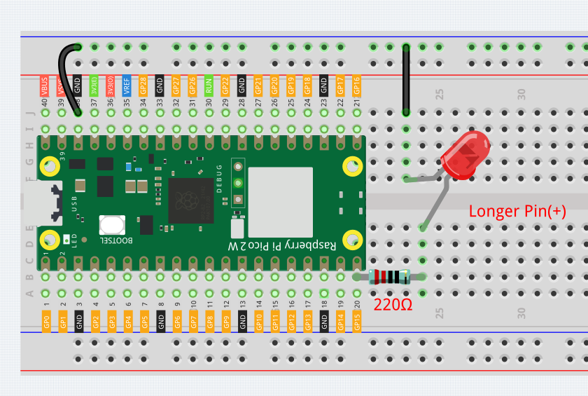
Wire slowly:
- Connect GP15 to the resistor path.
- Put the resistor in series with the LED.
- Put the LED cathode side toward GND.
- Connect the GND rail or row back to a Pico GND pin.
Before USB power goes in, trace the circuit with your finger from GP15 to GND. If your finger can skip the resistor, the circuit is wrong.
Code: blink GP15
from machine import Pin
from time import sleep

led = Pin(15, Pin.OUT)

while True:
    led.value(1)
    sleep(1)
    led.value(0)
    sleep(1)
How the code controls hardware
from machine import Pin imports the MicroPython class that talks to GPIO pins. The official MicroPython Pin docs describe a pin as an object you can configure for input or output.
led = Pin(15, Pin.OUT) creates a GPIO output object for GP15. The number 15 means GP15, not physical pin 15 on every diagram.
led.value(1) drives the output high. On this circuit, high means the LED path gets voltage and the LED lights.
led.value(0) drives the output low, so the LED turns off.
sleep(1) pauses the loop for one second so the blink is visible. Without the pause, the loop would switch too quickly for your eyes.
Debug checklist
If the LED stays dark:
- Flip the LED around. Polarity is the most common issue.
- Confirm the resistor is in series, not sitting in an unconnected row.
- Confirm the code uses Pin(15) and the wire actually goes to GP15.
- Confirm GND from the LED path reaches a Pico GND pin.
- Try the built-in LED lesson again to prove Thonny and the board still work.
If the LED is always on, the circuit may be connected to 3V3 instead of GP15, or the script from another run may still be active. Click Stop and re-check the row.
Remix: make a signal pattern
Try two changes:
1. Change both sleep values to 0.2 for a fast alert blink.
2. Make the on time short and the off time long, like sleep(0.1) then sleep(1.5).
Notice that you are not changing the circuit, only the timing logic.
Checkpoint
Mark complete when:
- Your external LED blinks from GP15.
- You can point to the resistor and explain why it is there.
- You can explain what led.value(1) and led.value(0) do.
- You tried at least one timing remix.
Private Dev Log
Write a short build note:
1. My LED circuit path was...
2. The wiring mistake I checked for was...
3. The blink pattern I made was...
References
Primary build reference:
https://docs.sunfounder.com/projects/pico-2w-kit/en/latest/pyproject/py_led.html
MicroPython API reference:
https://docs.micropython.org/en/latest/library/machine.Pin.html
ObsoleteHQ uses original lesson wording and code explanation while citing SunFounder wiring/source assets.