
001
Concept Lesson
Beginner
Meet Your Pico 2 W
Before the Pico 2 W obeys your code, learn the tiny map printed on the board.
Mission: meet the board
Today is a no-code scouting mission. Your job is to make the Pico 2 W feel less like a mystery rectangle and more like a tool you can name.
By the end, you should be able to pick up the board and find: the USB port, the main chip, the wireless area, the pin rows, the ground pins, and the 3.3V power pin.
Do not wire anything yet. This lesson is about knowing what you are holding before electricity gets involved.
Board tour
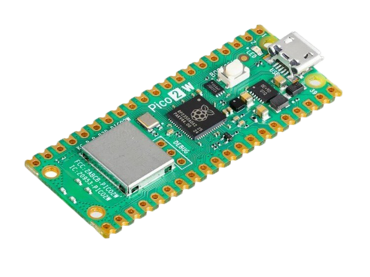
Look for these landmarks on your own board:
- USB port: the board's power and data doorway.
- BOOTSEL button: used during some setup and recovery steps.
- RP2350 chip: the brain that runs your MicroPython code later.
- Wireless hardware: what lets Pico 2 W join Wi-Fi and Bluetooth projects later.
- Two long pin rows: the places future circuits will connect.
Tiny check: hold your board so the USB port is at the top. Point to three things from the list before moving on.
Pin map survival rules
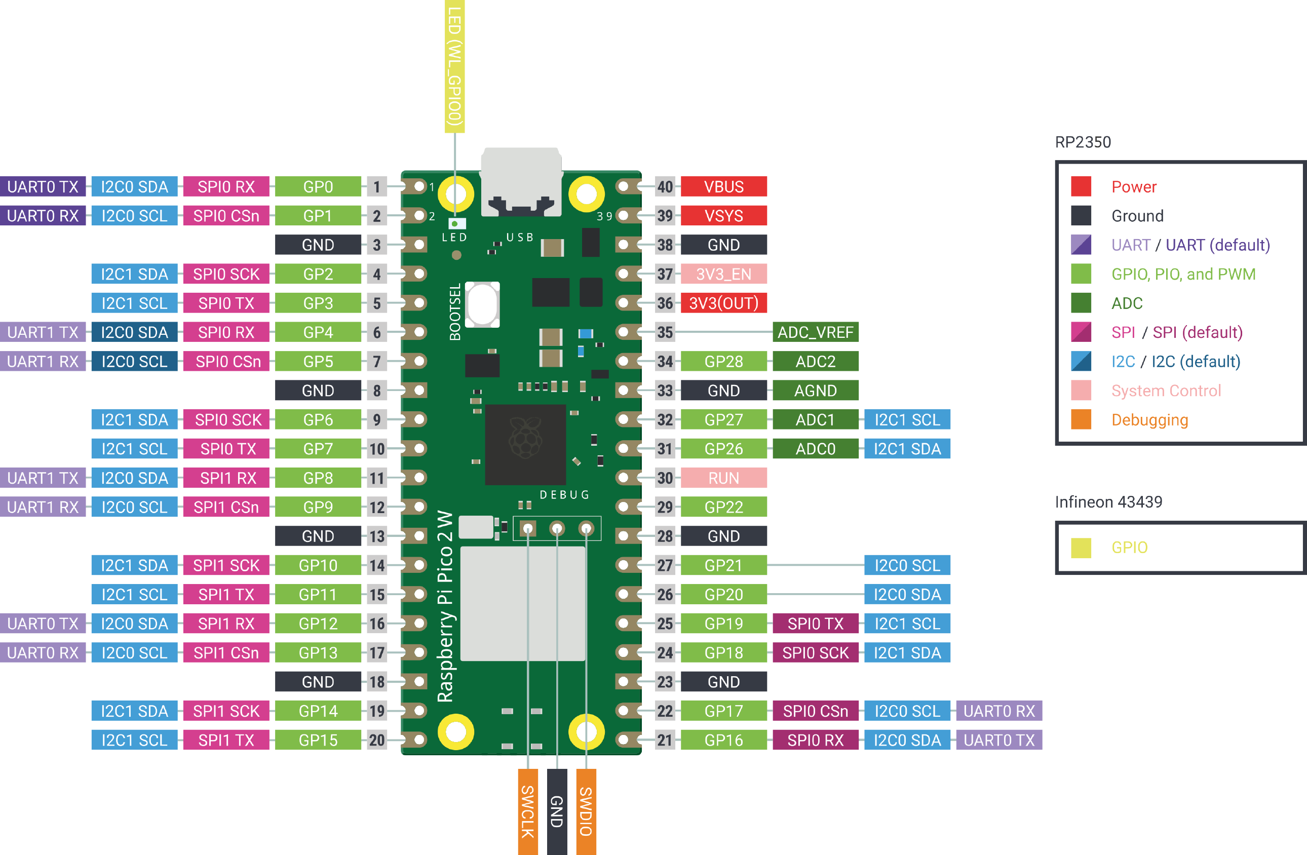
The pinout is your wiring map. You do not need to memorize it. You need to know how to read it.
Three rules matter right away:
1. GPIO pins are the general-purpose signal pins. They are for inputs and outputs.
2. GND means ground. Most circuits need a shared ground to behave.
3. Pico GPIO is 3.3V logic. Do not feed 5V signals into GPIO pins.
Some pins can do special jobs later, like analog input, I2C, SPI, UART, PWM, or power. For now, your power move is simple: check the pin label before plugging anything in.
Board detective checkpoint
Before you mark this lesson complete, do this no-code check:
- Point to the USB port.
- Point to BOOTSEL.
- Find one GND pin on the pinout.
- Find one GPIO pin on the pinout.
- Say out loud: GPIO pins need 3.3V-safe signals.
If you can do those five things, you are ready for the Thonny setup lesson.
Private Dev Log
Write two or three sentences:
1. One board part I can identify now is...
2. One pin-map rule I want to remember is...
3. One thing I want the Pico 2 W to do later is...
References and next step
Reference used for board facts and images:
https://docs.sunfounder.com/projects/pico-2w-kit/en/latest/introduction_to_pico_2w.html
Original image sources copied into this project with visible attribution:
https://docs.sunfounder.com/projects/pico-2w-kit/en/latest/_images/pico_2w_side.png
https://docs.sunfounder.com/projects/pico-2w-kit/en/latest/_images/pico-2-w-pinout.png
Next lesson: Thonny IDE Introduction. That is where setup begins. This lesson stays no-code on purpose.